Lesson Objectives
- Install and include the MFRC522 SPI library.
- Wire the RC522 to the Arduino using SPI (SS, MOSI, MISO, SCK).
- Read and print the UID of an RFID tag via
Serial.
- Capture and decode the SPI bus with Red Pitaya’s Logic Analyzer.
Theory
Modern embedded systems often rely on RFID for contactless identification—whether in access cards, inventory tracking, or payment. At the heart of many hobbyist and prototyping setups is the MFRC522 module, which speaks SPI to an Arduino to exchange commands and receive tag data.
- 13.56 MHz NFC/RFID:
The RC522 uses the ISO/IEC 14443A standard (MIFARE), operating at 13.56 MHz.
- SPI Interface:
SPI (Serial Peripheral Interface) provides a high-speed, full-duplex channel between the Arduino (master) and the RC522 (slave). Four data lines—MOSI, MISO, SCK, and SS—carry commands, clock pulses, and responses.


- UID Reading Workflow:
- Initialization: Arduino configures SPI and resets the MFRC522.
- Polling: The RC522 is queried for the presence of a tag.
- Select & Read: Upon detecting a tag, the Arduino issues a “read serial” command.
- Terminate: The tag is halted so the next scan cycle begins cleanly.
- Why Logic Analysis Matters:
While the Arduino’s
Serial.println() confirms the UID at the software level, a logic analyzer—like Red Pitaya’s built-in Digital Bus tool—lets you visualize the SPI waveforms, verify timings, decode the byte streams, and debug wiring or protocol errors at the bit level.Hardware Setup
A. Materials Required
- Red Pitaya STEMlab 125-14 (or compatible model)
- Arduino Uno or Arduino R4
- RC522 RFID Reader Module
- RFID Tags (MIFARE, 13.56 MHz)
- Jumper wires (male-to-female and male-to-male)
- Breadboard (optional, for clean wiring)
B. SPI Lines & Power Connections
Connect RFID sensor as shown:
RC522 Pin | Arduino Uno | Arduino R4 | Notes |
VCC | 5 V | 5 V | Power |
GND | GND | GND | Common ground |
SDA | D10 (SS) | D10 (SS) | “Slave Select”—chip-select |
SCK | D13 (SCK) | D13 | SPI clock |
MOSI | D11 (MOSI) | D11 | Master Out → RC522 In |
MISO | D12 (MISO) | D12 | RC522 Out → Master In |
RST | D9 | D9 | Module reset (any GPIO works) |
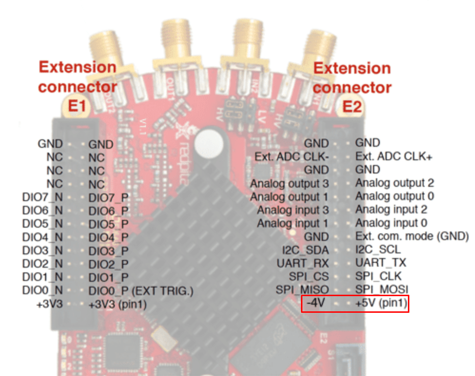
C. Oscilloscope conection
On your Red Pitaya oscilloscope connect as follows:
- DI00_P ↔ SCK,
- DI01_P ↔ MOSI,
- DI02_P ↔ MISO,
- DI03_P ↔ SS.
Procedure
A. Setting up the Code:
First let’s install a Library:
- In the Arduino IDE, go to Sketch → Include Library → Manage Libraries…
- Search for “MFRC522”.
- Locate “MFRC522” and click Install
Then:
- Upload code below to your Arduino.
- Open the Serial Monitor at 115200 baud.
- Present an RFID tag—its UID will print in HEX.
Code:
#include <SPI.h>
#include <MFRC522.h>

// Pin definitions
#define SS_PIN   10    // SDA on RC522
#define RST_PIN   9    // RST on RC522

MFRC522 mfrc(SS_PIN, RST_PIN);

void setup() {
  Serial.begin(115200);     // Open serial monitor @115200 baud
  while (!Serial) { }       // Wait for Serial on Leonardo/R4

  SPI.begin();              // Init hardware SPI
  mfrc.PCD_Init();          // Init MFRC522

  Serial.println(F("RC522 RFID Reader Initialized."));
  Serial.println(F("Scan a tag against the reader."));
}

void loop() {
  // Look for new cards
  if (!mfrc.PICC_IsNewCardPresent()) return;
  if (!mfrc.PICC_ReadCardSerial()) return;

  // Print UID
  Serial.print(F("Card UID:"));
  for (byte i = 0; i < mfrc.uid.size; i++) {
    Serial.print(mfrc.uid.uidByte[i] < 0x10 ? " 0" : " ");
    Serial.print(mfrc.uid.uidByte[i], HEX);
  }
  Serial.println();

  mfrc.PICC_HaltA();        // Halt PICC
  delay(500);               // Debounce
}
B. Capturing SPI on Red Pitaya
- Open Logic Analyzer on Red Pitaya.
- Enable DIN0 ↔ SCK, DIN1 ↔ MOSI, DIN2 ↔ MISO, and DIN3 ↔ SS.
- In the Digital → BUS menu select SPI.
- Hit RUN
You’ll see:
- SS goes LOW: start of transaction
- SCK pulses: clocking bits in/out
- MOSI frames (
0xcommands)
- MISO frames (UID bytes returned)
- SS goes HIGH: End of transaction
Analysis
- Verify that the UID bytes printed in Serial match those decoded on the logic analyzer.
- If SS doesn’t drop, check that D10 is set correctly in
MFRC522 mfrc(SS_PIN, RST_PIN).
- Use Settings → Time/div to zoom in on the SPI clock (D13).
Conclusion
With this exercise you’ve:
- Installed the MFRC522 SPI library.
- Wired SDA/SS, SCK, MOSI, MISO, RST, VCC, and GND correctly.
- Written and run a sketch to read tag UIDs over SPI.
- Captured and decoded the SPI bus with Red Pitaya.
These skills generalize to any SPI-based sensor or device—empowering you to both develop and debug at the signal level.
 Made with Bullet